Imagine you have a hub. You don’t know anything about it and can’t find any manufacturer specifications. However, it’s a really great hub that you love, and want to build a wheel on it!
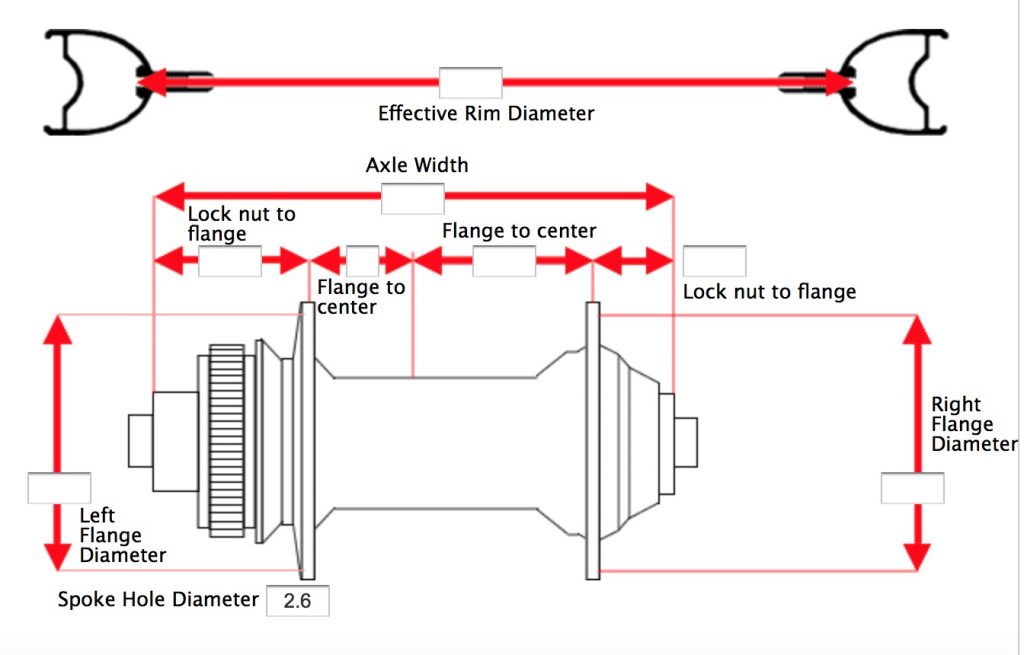
You can jump online and see how to find the parts you need to measure – this screen grab from the ProWheelBuilder.com spoke length calculator shows what you need to know.
The key observations are PCD – or the diameter of the spoke flanges; OLD – or the distance between the two hub end caps; locknut to flange – or the distance from each end cap to flange centres; and flange to centre – or the distance between the centre of the hub and the centre of each flange. For reference, the DT Swiss spoke calculator uses the same data.
But how do you get these data if you can’t look the hub up online?
I use a few simple tools. Here, I have some hubs; a pretty basic set of calipers, a right angle rule, a piece of corrugated card, and things to write with. It helps if the card has at least two edges at a proper right angle.
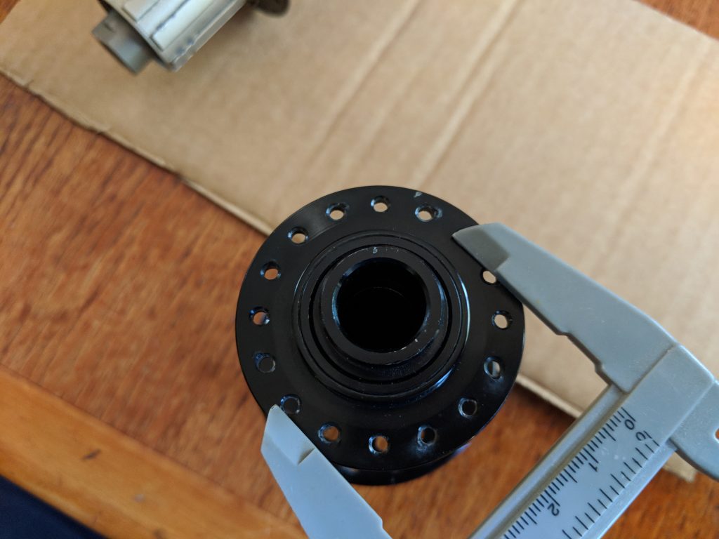
First thing is to measure PCD. That’s simple – use the caliper. You could also create a tool to measure this out of card – get creative!
Notice I’m not trying to measure the middle of the hole – just measure between the top of the hole on one side and the bottom of the hole on the other. It’s the same as centre-to-centre difference.
These hubs have different sized flanges, so I had to do this four times. Unlucky!
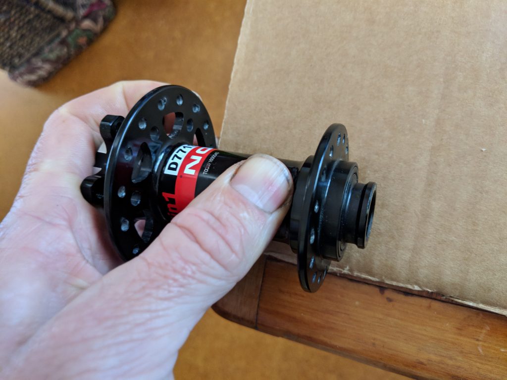
Next, measure the flange to flange difference. This is where the card comes in.
Here, since the flanges are different diameters I have the large flange off the edge of a table, pushed up hard against the edge of the card. I’m pressing down on the hub body hard enough that the smaller flange makes an impression in the card – you can mark each edge and hey presto – you can measure flange to flange!
Measure from the card edge to the far edge of the impression; and add the flange thickness (use the caliper to measure that).
If your hub has identical flanges, you can just push both into the card at once and make your life easier. Just ensure that your impressions are far enough into the card to allow for the whole hub to be measured up each side.
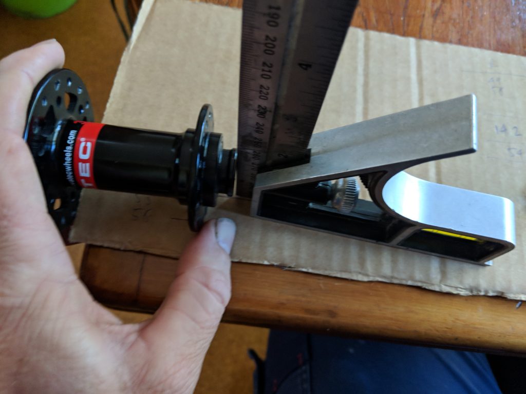
Next, taking the flange to locknut distance for one side. Here, use the right angle rule to ‘drop’ the end of your hub on the small flange side down to the card.
Again, for hubs with symmetrical flanges you can do this for both ends while the hub is still in it’s ‘impressions’ and save a bunch of effort. This time, however, we need to do it the long way and do some quick maths. Now that we know our OLD (hub spacing from end to end), our flange to flange distance and one locknut to flange distance we can infer the rest.
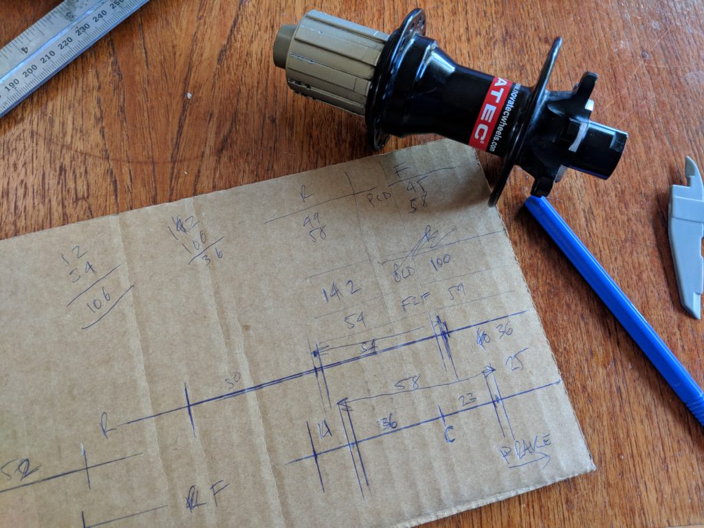
Mark out a couple of ‘axles’ and transfer your measurements across. From here, you can work out the hub centre; then the flange to centre from both sides.
In this picture, the rear hub is marked out at the top, and the front hub at the bottom. Note, I’ve transferred my measurements of the partial hub (from one flange across) from the other side of the card. This side also has a neat right angle to work from (upper right corner). Lining the hub up, it looks pretty good.
…and you’re done! Combined with your PCD measured at the start, you can go to a spoke calculator and determine which spokes you need!
So how did I go? I made:
PCD: (rear) 49/58 (front) 45/58
Brake side locknut to flange: (rear) 36 (front) 25
Drive side locknut to flange: (rear) 50 (front) 14
Flange to flange centre: (rear) 54 (front) 58
Flange to centre (brake/drive): (rear) 20/34 (front) 23/36
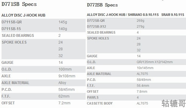
…and Novatecs own specs are here (from weightweenies.com). Note Novatec’s F2F measurement is from the outside of the flanges – not centres.
So not too bad! What’s the next step?
I usually use both prowheelbuilder.com and the DT Swiss calculator. If both are around the same, I go ahead and order spokes! If not, I check my measurements and try again.
For reference, I always use and recommend double butted spokes (or triple for heavy loads). Why? Because engineering – which you can googlify for now. A non-structural-engineer explanation is another whole post.
The pseudo-sales-pitch
Everything published at Tools for the revolution is free for you to use, licensed CCBY-4.0, and doesn’t use ads or tracking. You don’t need to subscribe, we don’t want any of your data.
If you find the content here useful to your self-discovery, business or entertainment, you can support production of more stories and open source geo-magick via Paypal; or hire me to do stuff; or invite me to come and talk to a bunch of you about anything here. Enjoy!
